
AutoCAD vs SOLIDWORKS: the quick answer
| Requirement | AutoCAD | SOLIDWORKS |
|---|---|---|
| 2D technical drafting | Excellent | Very good |
| DWG files | Excellent | Compatible |
| 3D modeling | Yes | Excellent |
| Parametric modeling | Possible depending on the tools used | Core functionality |
| Mechanical assemblies | Limited | Excellent |
| Drawings from a 3D model | Possible | Excellent |
| BOMs | Yes, particularly with AutoCAD Mechanical | Yes |
| Mechanical simulation | Limited | SOLIDWORKS Simulation solutions |
| Machine design | Possible | Excellent |
| Architecture / building plans | Very well suited | Less suitable |
| Product development | Possible | Very well suited |
AutoCAD and SOLIDWORKS can both be used to create technical drawings and 3D models, but they are designed for different needs. AutoCAD is particularly well suited to 2D drafting and DWG-based environments, while SOLIDWORKS is primarily designed for parametric 3D mechanical design, assemblies and product development.
What is AutoCAD?
AutoCAD is CAD software developed by Autodesk.
Historically associated with 2D technical drafting and the DWG format, AutoCAD also supports 3D modeling with solids, surfaces, and meshes.
AutoCAD 2026 also includes several specialized toolsets, including:
- AutoCAD Mechanical;
- AutoCAD Electrical;
- Architecture;
- Map 3D;
- Plant 3D;
Autodesk also offers AutoCAD on the web and on mobile.
For a company that exchanges a large volume of DWG drawings with its clients, architects, suppliers, or subcontractors, this ecosystem is one of AutoCAD’s main advantages.
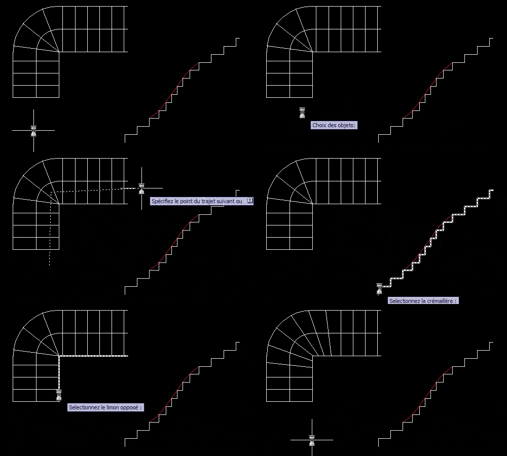
Example of a stair drawing in AutoCAD
Parametric vs static drawings
This is probably one of SOLIDWORKS’ most important advantages for a manufacturer.
In SOLIDWORKS, a drawing is a CONSEQUENCE of the 3D design. In AutoCAD, you have to draft the drawing manually.
Let us take the example of changing a dimension in a part:
850 mm → 920 mm -> the model changes.
In SOLIDWORKS: The corresponding view in the drawing updates (front, side, section, and detail views remain linked to the same model).
In AutoCAD: You must update EACH view manually

Each view in this drawing is generated automatically by SOLIDWORKS
AutoCAD does have parametric constraints and tools to automate certain designs, but it does not natively follow the same associative 3D mechanical model → linked drawing → manufacturing logic as SOLIDWORKS.
For a manufacturer producing many variants of the same product, this difference can become significant.
SOLIDWORKS manufacturing modules: sheet metal and weldments
SOLIDWORKS enables design based on the manufacturing trade
Two examples are particularly relevant for manufacturers of stairs, structures, and industrial equipment:
Weldments and sheet metal parts
Weldments: design a structure and automatically generate a cut list
Imagine a guardrail or a frame made of rectangular tubing.
In a general-purpose CAD program, it is possible to draw or model each of these tubes.
SOLIDWORKS goes further with its Weldments environment.
The designer can create a structure from standard profiles:
- Square/rectangular tubes
- Angle irons
- U/H/L profiles or custom structural profiles;
SOLIDWORKS then calculates the different segments required for manufacturing.
It can generate a cut list — Cut List — indicating, among other things, the different elements of the structure.
For example:
Profile Quantity Length
Tube 2″ × 2″ 4 1,200 mm
Tube 2″ × 2″ 8 850 mm
Tube 1″ × 1″ 12 950 mm

SOLIDWORKS can generate cut lists for manufacturing
For a manufacturer of stairs, guardrails, frames, or welded structures, this brings CAD directly closer to the reality of the shop floor.
AutoCAD can of course draw these profiles, and AutoCAD Mechanical includes bill of materials functions.
However, standard AutoCAD does not offer the same 3D weldments environment with associative cut list generation.
Sheet metal: automatically go from the bent part to the flat pattern
The same logic applies to sheet metal.
Suppose a company manufactures a step, a cover, or a bent plate.
In SOLIDWORKS, the part can be designed directly as a sheet metal part.
The software takes into account, among other things:
- Thickness
- Bends
- Bend radius
- Cutouts
- Reliefs
- The K-factor or bend calculation parameters.
SOLIDWORKS can then automatically generate the part’s flat pattern.
In other words:
3D bent part → Flat Pattern → DXF for laser cutting
The designer therefore works on the part as it will actually exist once manufactured, while SOLIDWORKS can calculate the geometry required before bending.
This is extremely useful for:
- Laser/plasma/waterjet cutting
- Punching;
- Preparing parts before bending.
If a part dimension changes, the flat pattern can also be recalculated.

SOLIDWORKS can flatten sheet metal and generate the bend table
AutoCAD can of course be used to manually draw a flat pattern.
However, standard AutoCAD does not have an equivalent sheet metal environment that can automatically go from a parametric bent part to its flat pattern.
SOLIDWORKS is particularly powerful for assemblies
Imagine you are designing a machine made up of:
- 350 parts
- Motors/bearings/profiles/plates
- Bolts/cylinders
- Machined parts.
In SOLIDWORKS, each component can be created individually and then integrated into an assembly.
Mates then define how components behave relative to one another.
This makes it possible to check:
- Interferences
- Motion
- Clearances;
- Component positioning
- Mass properties;
- The assembly structure.
This is precisely the type of workflow that explains why SOLIDWORKS is widely used by machine and industrial equipment manufacturers.

SOLIDWORKS helps you better visualize the structure of your staircase and immerse your client
Simulate/test your products before manufacturing
SOLIDWORKS can also integrate simulation tools directly into the design environment.
Depending on the solution used, it is possible to study, among other things:
- Stresses
- Displacements
- Safety factors
- Vibration
- Thermal/buckling
- Fatigue.
SOLIDWORKS also offers solutions dedicated to more advanced analyses.
The benefit is being able to perform certain validations even before building the prototype.
AutoCAD is not primarily positioned as a mechanical simulation platform.
For companies that want to integrate calculation and validation directly into their design process, SOLIDWORKS therefore has a major advantage.

Once the design is complete, the designer can run a load study
AutoCAD vs SOLIDWORKS: two tools for two different approaches
Simply pitting AutoCAD against SOLIDWORKS ultimately amounts to comparing two different approaches to CAD.
AutoCAD remains a reference for technical drafting and DWG.
SOLIDWORKS focuses more on parametric 3D mechanical design and product development.
For a manufacturing company that currently designs its machines mainly in 2D, the real question may therefore be less:
“AutoCAD or SOLIDWORKS?”
and more:
“Should our design process still be primarily based on 2D drafting?”
Not sure whether to choose AutoCAD or SOLIDWORKS?
Kotona Vision can review your current design methods and show you concretely how your own projects could be completed in SOLIDWORKS.
Request a demo →Frequently Asked Questions
FAQ – AutoCAD vs SOLIDWORKS
Can SOLIDWORKS replace AutoCAD?
In a company specializing in mechanical design, often yes for a large part of the design process. However, an organization that mainly does 2D drafting or must constantly work with DWG files may keep AutoCAD or another 2D CAD program.
Can AutoCAD do 3D?
Yes. AutoCAD can create solids, surfaces, and 3D models. However, SOLIDWORKS is more specialized in parametric mechanical design and the creation of complex assemblies.
Is AutoCAD Mechanical comparable to SOLIDWORKS?
AutoCAD Mechanical adds many mechanical drafting tools to AutoCAD, including standard libraries and bill of materials functions. SOLIDWORKS is more oriented toward complete 3D design of a product or machine, with linked parts, assemblies, and drawings.
Which software should you choose to design a machine?
For complete machine design with linked parts, assemblies, drawings, and bills of materials , SOLIDWORKS is generally better suited to this type of workflow.
Which software should you choose if you mainly work with DWGs?
AutoCAD remains particularly well suited when creating and editing DWG files is at the core of day-to-day work.
Can AutoCAD and SOLIDWORKS be used in the same company?
Yes. Some companies, for example, use SOLIDWORKS for 3D mechanical design and AutoCAD for certain 2D drawings, layouts, or files coming from clients and suppliers.