
Why export a SOLIDWORKS part to DXF format?
The role of DXF format in the manufacturing process
The DXF format is widely used to transfer 2D geometry between design software and manufacturing equipment or software. It often serves as the link between the model designed in SOLIDWORKS and the next step in the industrial process.
A DXF file can specifically be used for:
- Laser / plasma / waterjet cutting
- Punching / CNC machines
- Nesting software
- Manufacturing subcontractors
However, a DXF file is not automatically ready for manufacturing. Its content must meet the recipient’s requirements: correct scale, consistent orientation, closed contours, absence of unnecessary geometry, and appropriate handling of bend lines. A good export method must therefore produce a reliable file, not just convert an extension.
The specific case of sheet metal parts
A sheet metal part designed in 3D must generally be exported in its flat pattern form.
Elements that can be included in the DXF:
- Outer contours
- Cutouts and holes
- Bend lines
- Sketches
- Custom layers
Why manual export quickly becomes restrictive
For a single part, manual export is fast. However, for an assembly consisting of many sheet metal parts, the same method requires opening files successively, selecting the correct flat pattern, checking options, and saving each DXF.
As volume increases, several difficulties arise:
- Successively opening each part
- Manual selection of the flat pattern;
- Repeated selection of export options;
- File creation and filing;
- Inconsistencies in naming;
- Missing a part or a configuration;
The problem is not the difficulty of an individual export. It lies in the repetition of the operation and the need for a uniform result. This is precisely what automation methods seek to solve.

For each DXF creation, the SOLIDWORKS user must manually generate the DXF through a series of steps
4 methods to export DXF files from SOLIDWORKS
| Method | Recommended use | Automation | Customization |
|---|---|---|---|
| Manual export | Occasional exports of a few parts | Low | Low |
| Task Scheduler | Converting multiple documents | Medium | Limited |
| SOLIDWORKS macro | Frequent exports of sheet metal parts | High | High |
| 3DEXPERIENCE workflow | Structured manufacturing process | Very high | Very high |
Method 1: Manual export from SOLIDWORKS
Manual export is the simplest method for a few parts. Open the sheet metal part, select a planar face or the flat pattern in the FeatureManager tree, then choose Export to DXF/DWG.
The process is as follows:
- Open the sheet metal part;
- Select a planar face or the flat pattern;
- Launch Export to DXF/DWG;
- Choose the entities to export;
- Check orientation and preview;
- Name and save the file.
It is also possible to use File > Save As, then select the DXF format. Official SOLIDWORKS documentation outlines the available options.
Options depend on the manufacturing process. Contours to be cut must be kept, while bend lines can be removed or placed on a separate layer. Sketches should only be included if they provide useful information to the shop floor.
The DXF should generally be exported at a 1:1 scale. Consistent orientation also simplifies its import into cutting and nesting software. If the software or machine handles splines poorly, they can be converted to polylines, provided sufficient precision is maintained.
Advantages and limitations of manual export
Manual export requires no additional tools and allows for control over each file. It is therefore suitable for occasional needs.
On the other hand, it becomes slow and repetitive when an assembly contains many parts. Naming, filing, and options rely entirely on the user, which increases the risk of error or omission.

Method 2: Exporting multiple files using Task Scheduler
Task Scheduler allows you to convert multiple SOLIDWORKS documents to various formats, including DXF and DWG. The user selects the files or a folder, configures the task, and then chooses the execution time.
This method avoids opening each document separately and allows conversions to be run outside of working hours. The availability of certain functions may depend on the SOLIDWORKS edition and version. SOLIDWORKS documentation details this feature.
How to schedule a DXF export?
- Open SOLIDWORKS Task Scheduler
- Select Export Files
- Add the documents or folder to be processed
- Choose DXF format
- Define the destination folder
- Choose the execution time
- Launch the task and check its status
The Scheduler is primarily suited for converting documents that are already prepared. Converting multiple drawings to DXF is not equivalent to automatically detecting all sheet metal flat patterns in an assembly.
When is this method useful?
The Scheduler is relevant when multiple files need to be converted with the same parameters. It allows for processing an entire folder, scheduling the conversion, and reducing manual handling.
However, its capabilities remain limited when it comes to browsing an assembly, recognizing sheet metal parts, handling multiple configurations, or building file names from SOLIDWORKS properties. For this type of logic, a macro is generally more suitable.
Additionally, SOLIDWORKS Task Scheduler is now included with all SOLIDWORKS Design licenses—even Standard! If you’re using an older version, we recommend considering an upgrade.
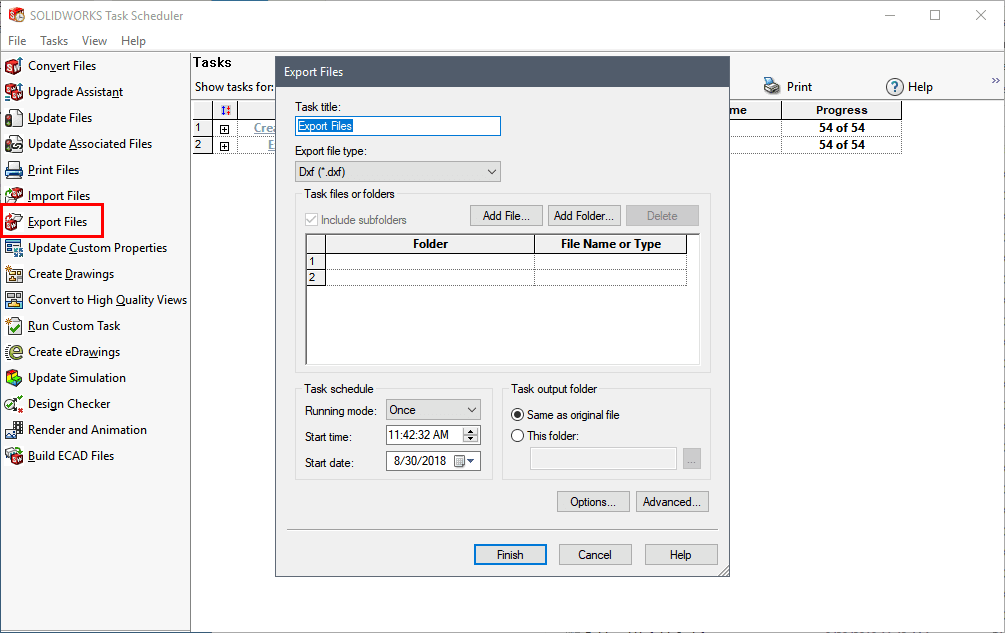
Task Scheduler can be launched from Windows or you can find it by typing “Task Scheduler” in the Windows search bar
Method 3: Automating export via a SOLIDWORKS macro
A macro uses the SOLIDWORKS API to automate operations normally performed by the user. It can browse a part or an assembly, identify sheet metal components, and export their flat patterns to DXF format.
It can also apply specific rules: select certain configurations, name files, choose their location, and report errors. The user then launches a single command instead of exporting each part separately.
What operations can be automated?
A macro can specifically:
- Export all flat patterns from an assembly
- Process multiple bodies or configurations
- Ignore certain components
- Exclude bend lines
- Classify files by project, material, or thickness
- Simultaneously generate DXF, PDF, or STEP files
- Produce a report of exports and errors.
The name can also be built automatically according to a convention such as:
Part Number – Revision – Material – Thickness.dxf
The main advantage is not just speed. The macro makes exports more uniform and less dependent on individual user habits.
Can I download a DXF export macro for free?
Yes. Free macros are available on forums and specialized sites. CodeStack, for example, offers a macro for exporting sheet metal flat patterns from a part or an assembly.
Before using it in production, check its compatibility with your SOLIDWORKS version, its naming rules, its configuration management, and its behavior in case of error. A macro designed for a simple assembly may be unsuitable for multibody parts, virtual components, or your company’s custom properties.
Important note as of August 26, 2026: AI included in SOLIDWORKS can now generate functional VBA macros, as demonstrated in our article on the subject: https://kotonavision.com/solidworks-ia-avenir-cao/
Advantages and limitations of a macro
Macros offer targeted, fast, and highly customizable automation. They run directly from SOLIDWORKS and often represent a good compromise for automating repetitive exports.
However, they remain dependent on file structure and must be maintained when the process changes. They do not necessarily control the data lifecycle: if the user opens an old revision, the macro may quickly export the wrong file.
We can help you program your first macros through our custom services

The possibilities for generating VBA macro(s) from LEO AI are in their early stages, but we can already predict a promising future for AI capabilities
Method 4: Integrating DXF export into a custom 3DEXPERIENCE workflow
From task automation to process automation
A macro primarily automates the action of exporting. A custom 3DEXPERIENCE workflow integrates this action into a broader validation and manufacturing release process.
The export can then depend on maturity status, revision, or approval. The workflow can also notify relevant personnel and keep a record of validations. This approach requires appropriate configuration: it is not a universal button ready to process any assembly.
What events can trigger the creation of a DXF?
Generation can be triggered during:
- Transition to “Approved for Manufacturing” status;
- Approval of a new revision;
- Validation by the production manager;
- Addition to a manufacturing batch;
- A request for transmission to a supplier.
The trigger and approval rules must match the company’s actual operations.
What files can be generated?
Depending on the configured process, several formats can be prepared: DXF or DWG for 2D data, PDF for drawings, and STEP for 3D exchange.
The 3DEXPERIENCE platform supports various derived formats. Documentation on CAD data export specifically mentions DXF, DWG, PDF, and STEP formats. The exact method must, however, be validated based on source data and available roles.
Advantages of a workflow connected to 3DEXPERIENCE
The workflow primarily allows for better control over the creation and distribution of manufacturing data. It improves revision management, standardizes the process, and reduces the risk of sending an old file.
It is particularly relevant for companies managing multiple designers, projects, or suppliers and using a formal approval process. For a few occasional exports, this solution would generally be disproportionate.
Additionally, the 3DEXPERIENCE platform is now included with your SOLIDWORKS subscription at no additional cost.
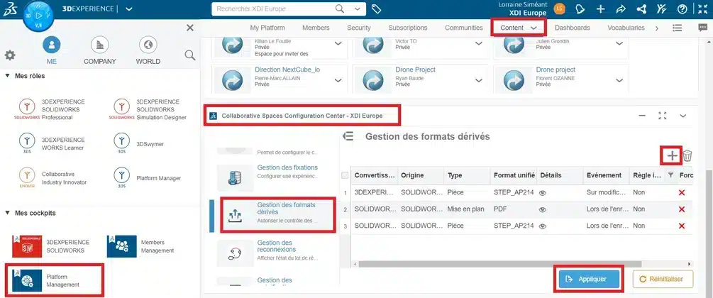
3DEXPERIENCE allows you to manage the automation of this export process through a central interface
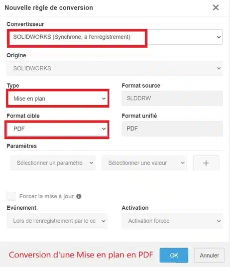
The task is completely customized based on a predefined workflow
Conclusion: Choosing the right level of DXF export automation
Manual export remains suitable when a company processes only a few DXF files. For occasional batch conversions, Task Scheduler already helps reduce manual handling.
However, a SOLIDWORKS macro becomes more relevant for automating flat patterns, their naming, and their filing.
When revisions and approvals also need to be controlled, a 3DEXPERIENCE workflow offers a more comprehensive approach.
The right level of automation therefore depends primarily on the volume of exports and the complexity of the manufacturing process.
Frequently Asked Questions
Frequently Asked Questions about DXF export in SOLIDWORKS
How to export a SOLIDWORKS sheet metal part to DXF?
Select a planar face or the flat pattern, then choose Export to DXF/DWG. Select the entities, check the preview, and save the file.
Can you export multiple SOLIDWORKS parts to DXF at the same time?
Yes. The Scheduler can convert multiple documents. To automatically detect sheet metal parts in an assembly, a macro is generally more suitable.
How to export all flat patterns from an assembly?
A macro can browse the assembly, identify sheet metal components, and export their flat patterns according to predefined rules.
Can Task Scheduler export DXF files?
Yes, but it does not always replace a specialized macro when you need to automatically process flat patterns from an assembly.
Can a DXF be generated after a part is approved?
Yes, this logic can be integrated into a custom workflow, depending on the roles and rules configured in 3DEXPERIENCE.
What is the difference between DXF and DWG?
DWG is primarily a native drawing format, while DXF is commonly used as an exchange format with manufacturing software.
Should bend lines appear in the DXF?
This depends on the shop floor. They are generally excluded from cut contours or placed on a separate layer.